If you’re a bit (nerdy and paranoid) like me, you probably are never really satisfied by using the ISP supplied modem/router device. My current ISP (Delta/Caiway) provides their fiber customers a Genexis device. This device is quite limited in (security) features, but most important of all it does not provide the option to be configured into L2 bridge! Having your ISP device in bridge would allow a customer to use a router device of choice without a nasty double NAT configuration.
Since bridging is not op an option I have been running a double NAT setup for a while, Finally I found a decent solution. The goal is to convert the fiber into a generic copper wire (UTP) which will provide the most options in terms of choice of devices. In this blog post I document the solution, the required components and how to put it all together. I hope this information can benefit other Delta/Caiway customers!
Original setup
| Component | Vendor / product | Image |
|---|---|---|
| Fiber Termination Unit (FTU) | Attema B.V. Universal FTU | |
| Modem/router | Genexis Platform 8740 |
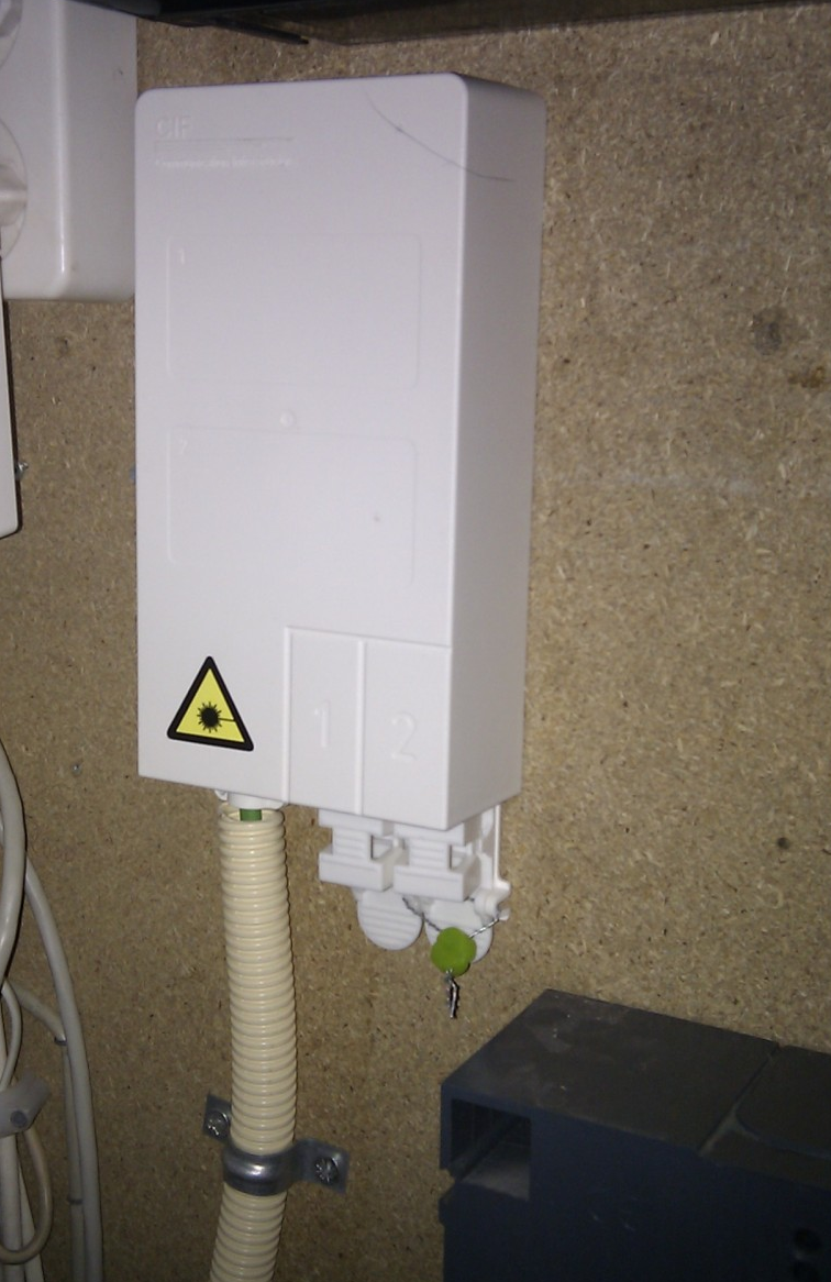
The FTU is the ISP owned piece of equipment and is basically the demcarcation point of responsibilities between their network and your home. When the service is delivered by the ISP the Genexis modem/router is directly connected to the FTU.
Required components
Since my home network was already mostly Ubiquiti based I tried to find the required components from their portfolio first, and luckilhy that proved to be no problem!
| Component | Vendor / product | Image |
|---|---|---|
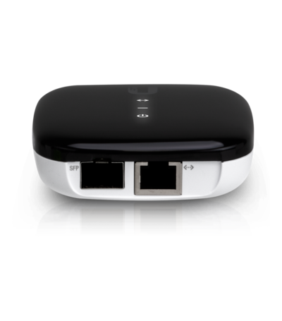
| Fiber to Ethernet converter | Ubiquiti - UF-AE | |
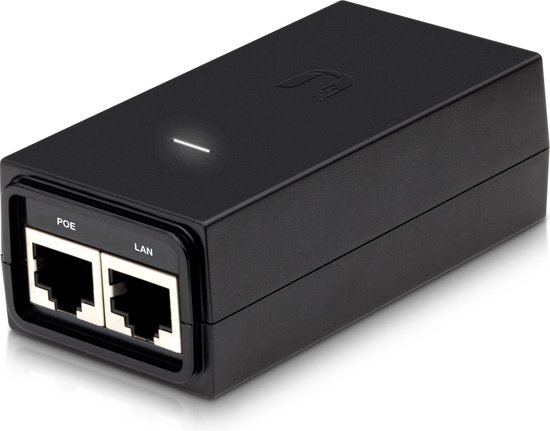
| POE injector | POE-24-12W-G 24V PoE injector | |
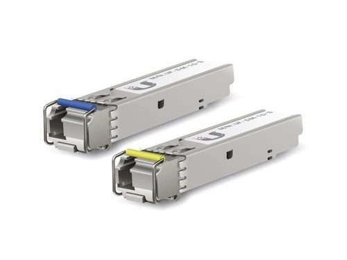
| Fiber module (SFP) | Ubiquiti UF-SM-1G-S (BiDi) | |
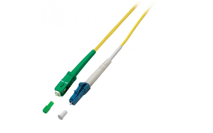
| Fiber cable | SC/APC (green connector) to LC/PC (blue connector) |
Steps
- Disconnect the Genexis router
- Wallmount components
- Install the new cable into the FTU connector
- Connect all the wiring
- Configure router
1. Disconnect the Genexis router
You need to remove the FTU connector that holds the fiber cable, most likely it’s installed in slot 1 on the FTU. Grab the connector at the bottom and slightly bend the connector towards you (from the wall) and gently pull down. In my case there was another FTU connector installed in slot 2 on the FTU which we will use later. So I decided to leave the fiber cable installed in the FTU connector (see picture). This also allows for quick restoration of the original setup if that would ever be needed; perhaps in case of service failures and engaging with helpdesk.
2. Wallmount components
POE injector
This step is pretty much self explanatory, just mount it close to a power wall outlet as the supplied power cable is rather short.
Fiber to Ethernet converter
When mounting the media converter take the fiber cable length into account. Mine is wallmounted pretty close to the FTU as I have only a 1m fiber cable, also I hate excessive cabling!
3. Install cable into the FTU connector
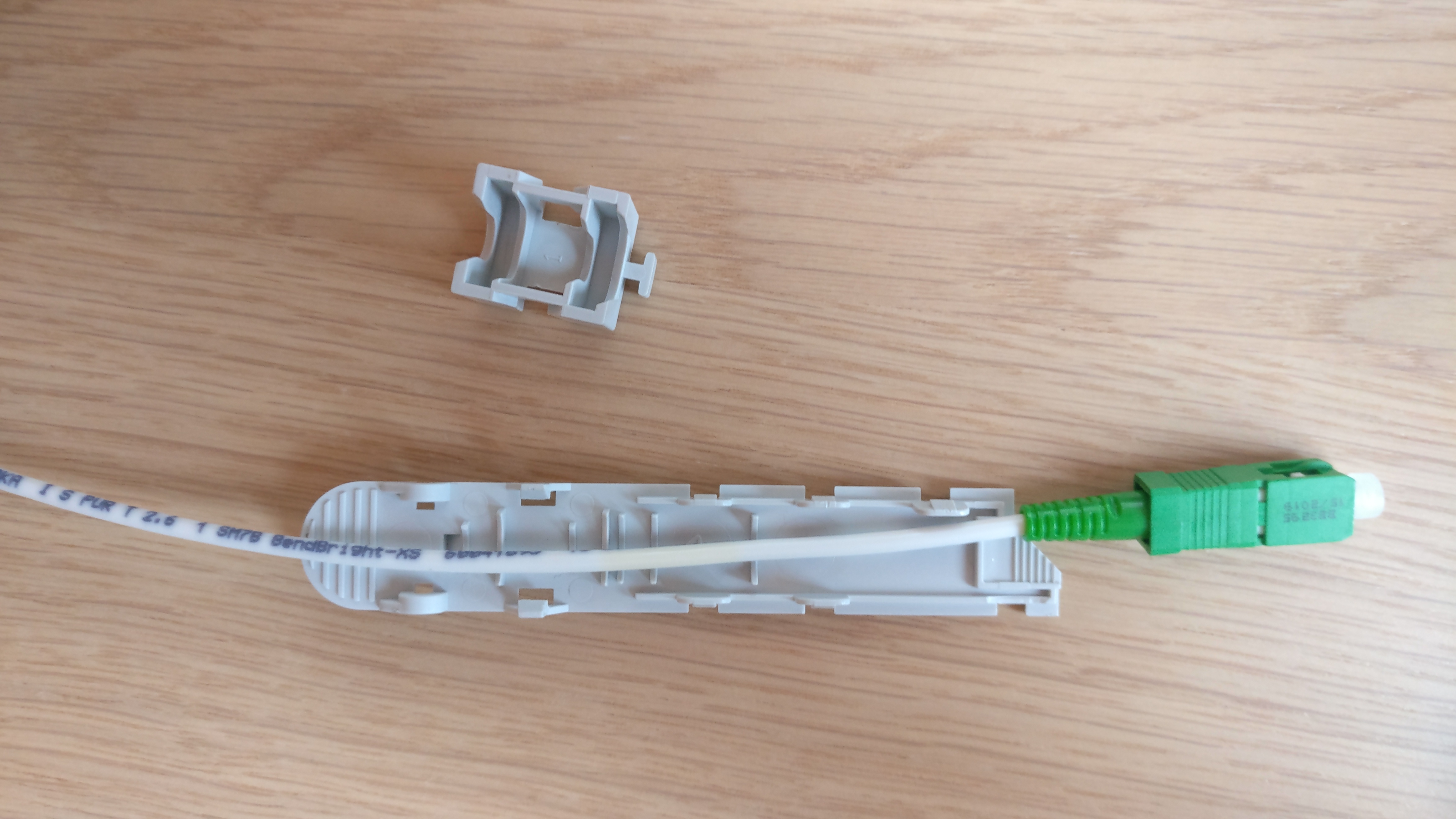
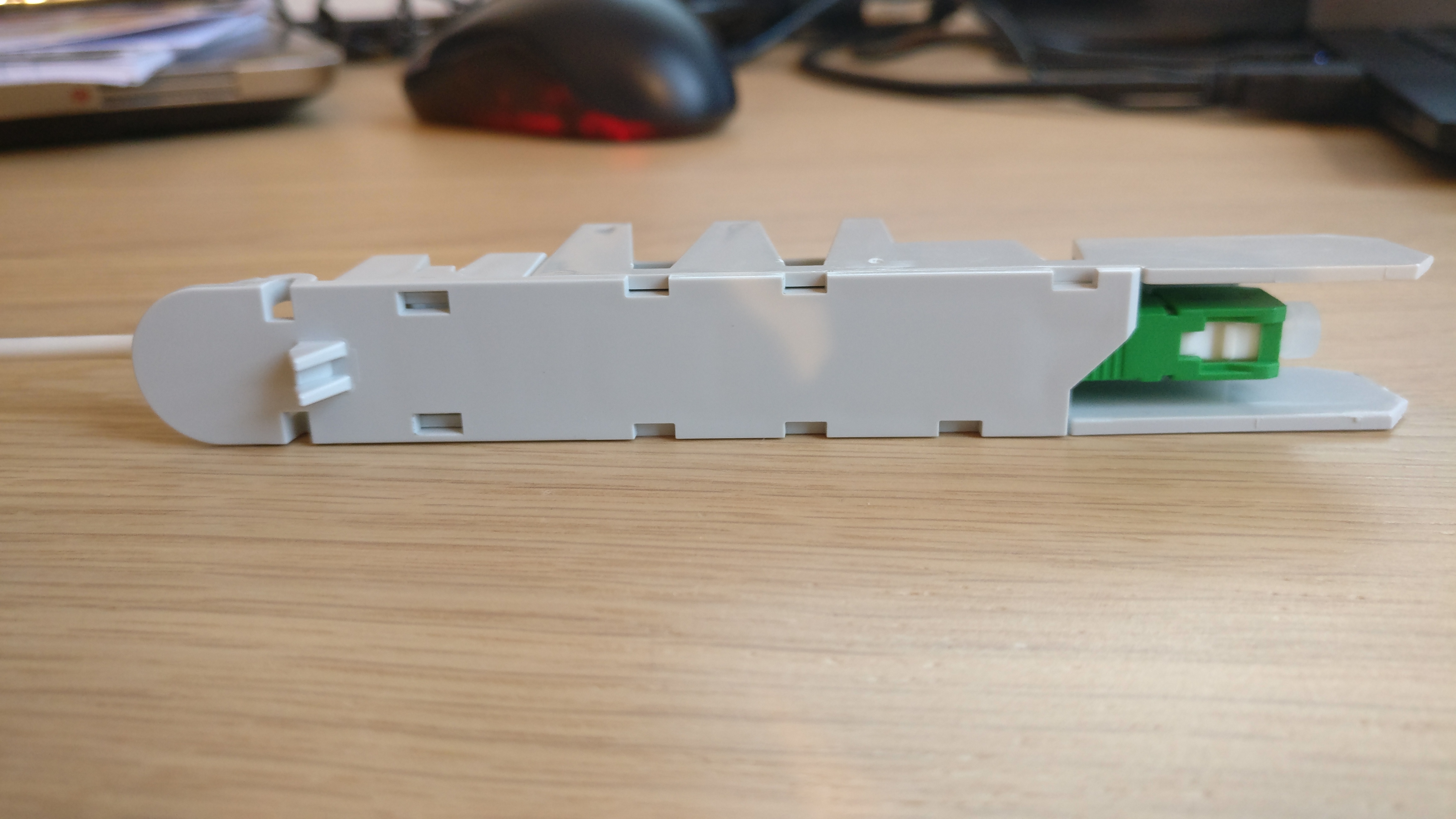
This will be a bit of fiddling! Remove the FTU connector from the second slot on the FTU. Now, we need to remove the cover by gently pressing the clips marked in the red circels. For this I’ve used a small screwdriver, and worked from right to left. While pressing the clips push the baseplate away from the cover.
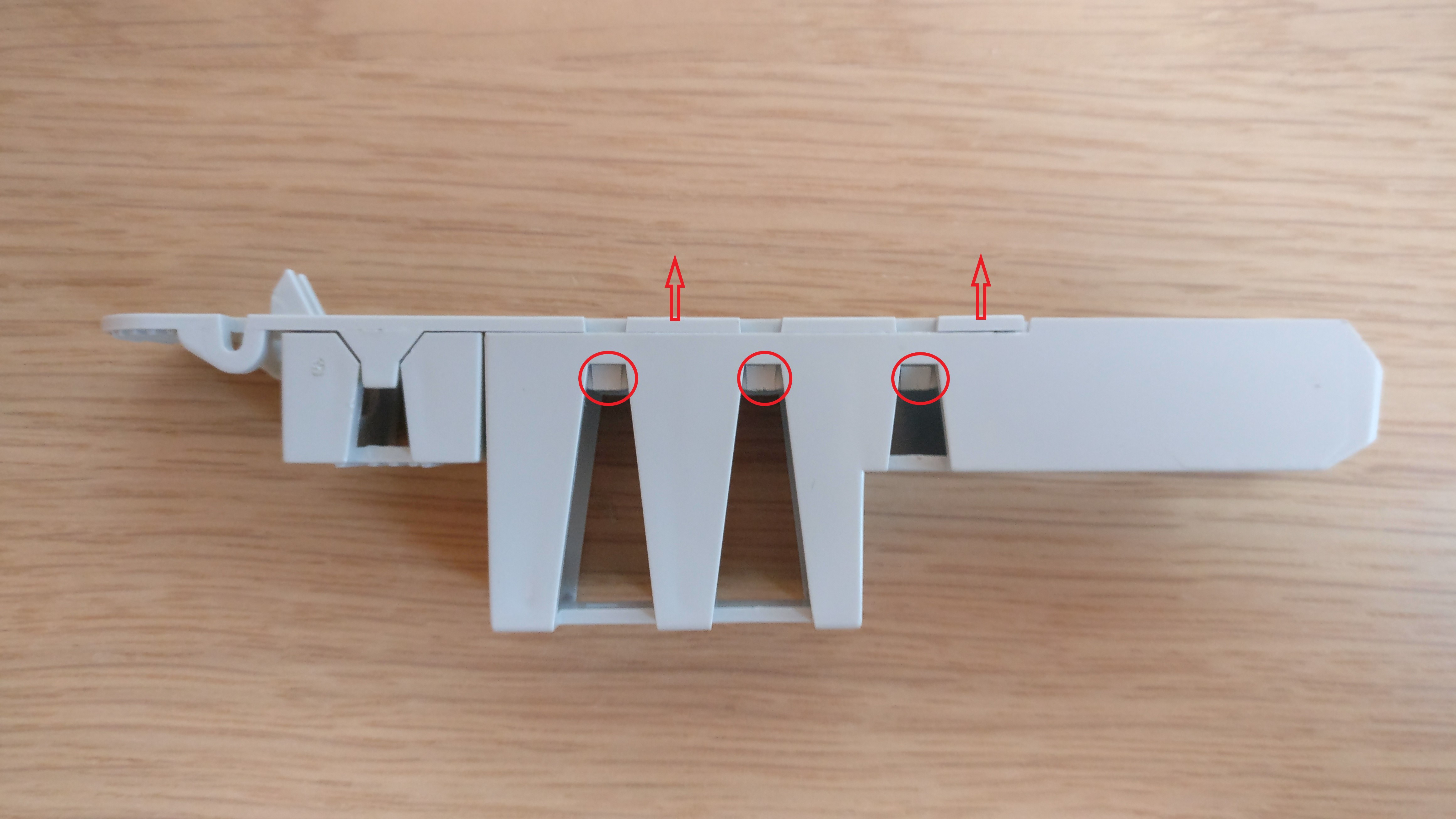
On the baseplate another smaller cover is mounted, this one needs to be removed as well! Using the screwdriver, gently push the clips outwards and pull the cover from the base plate.
The next step is to put the fiber cable with the SC/APC side (green connector) on the baseplate.
Then put the cover back onto the baseplate.
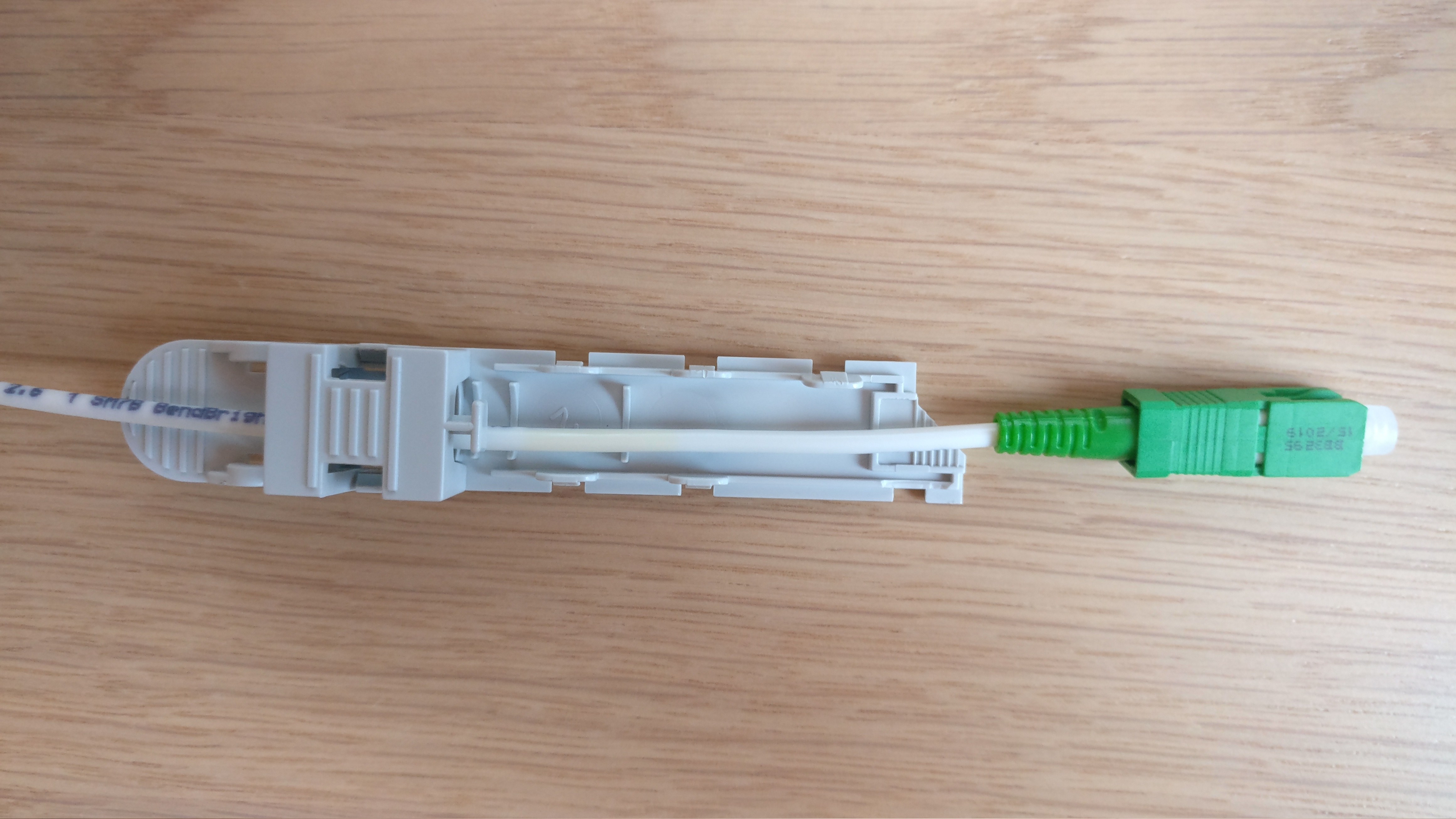
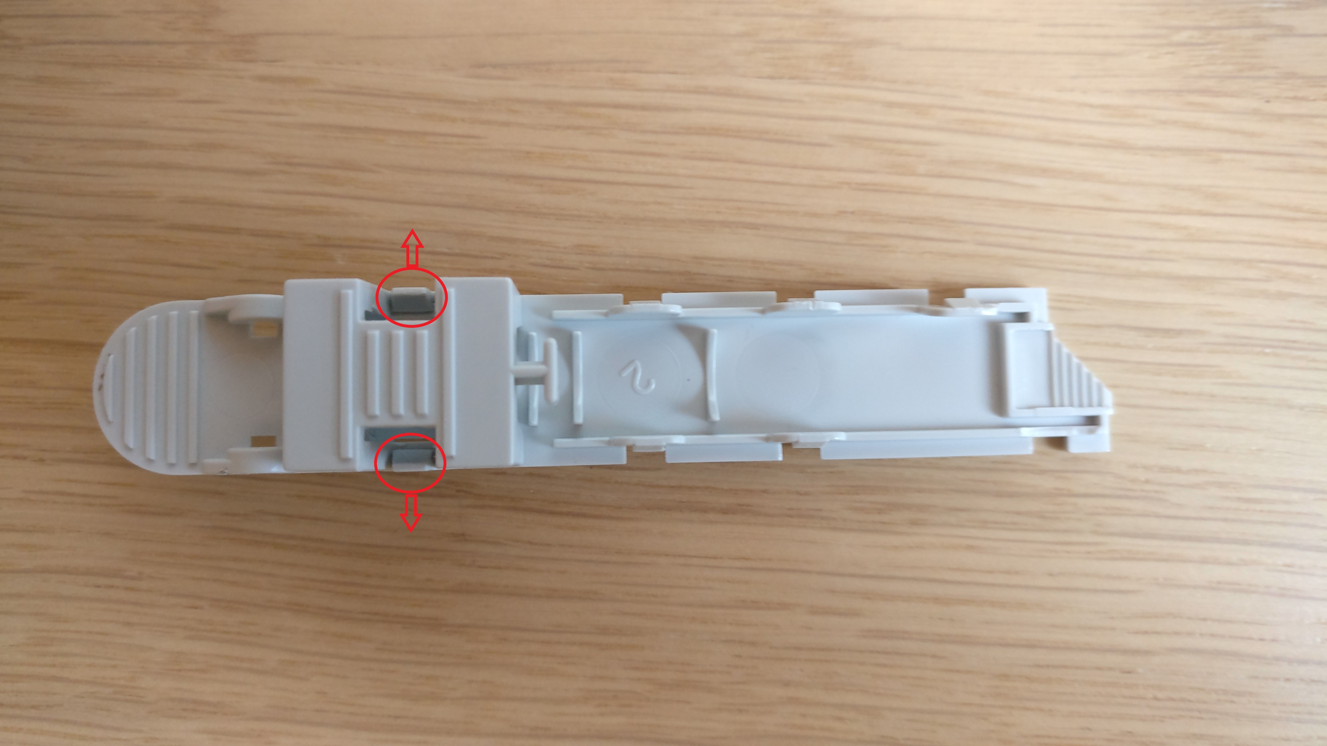
Now we place the fiber connector into the large cover. Make sure that the connector sits in the right position, at this point the connector will not be mounted firmly.
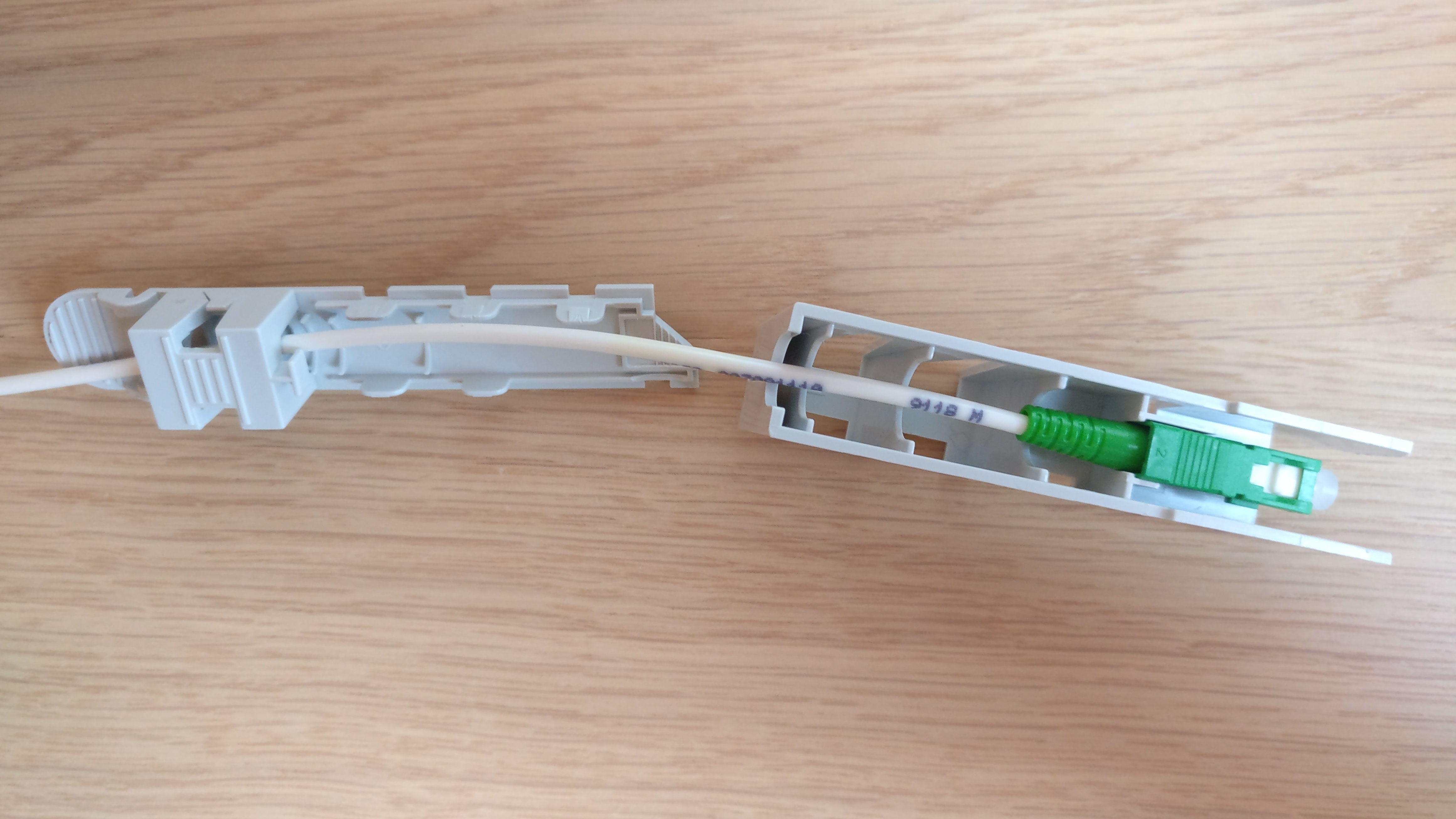
Flip the baseplate and the cover to their sides and push the cover onto the baseplate. To keep the connector in the right position you need to need to apply a bit of tension on the fiber cable by pulling it a bit while mounting the cover onto the baseplate. The connector will be fitted firmly after the cover is mounted onto the baseplate.
When everything is done correctly the end result looks something like this.
4. Connect all the wiring
Connect fiber
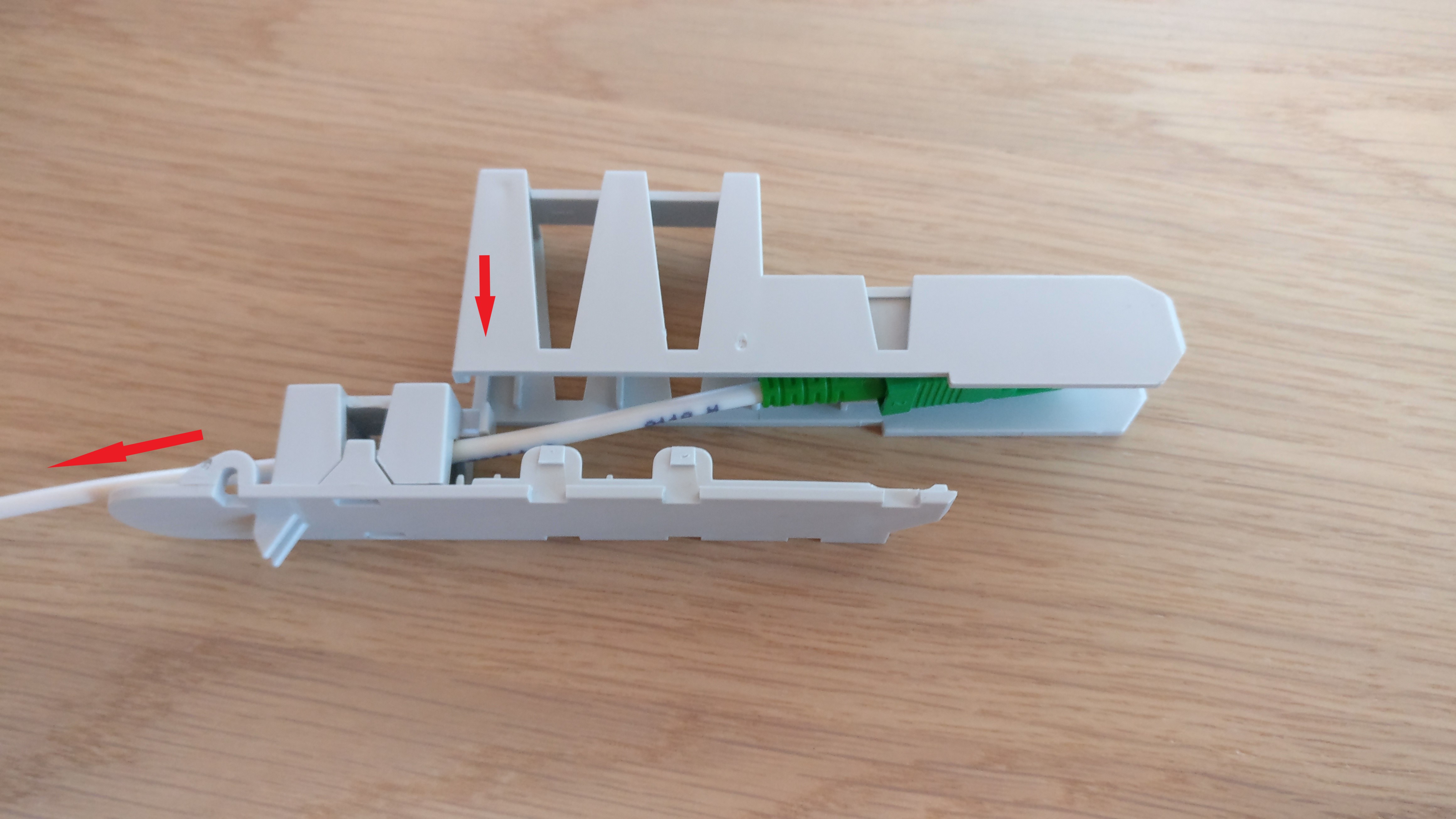
First we need to install the correct SFP into the Fiber to Ethernet converter, in this case that would be the blue SFP (1310nm-TX, 1550nm-RX). Then we need to install the FTU connector in slot 1 on, don’t forget to remove the protective caps from both ends from the cable first. Finally connect the blue connector into the SFP on the Fiber to Ethernet converter.
Connect POE injector
Install an UTP (cat 6/7) cable from the POE injector (use the port labeled as ‘POE’) to the Ethernet port on the media converter, then plug in the power connection.
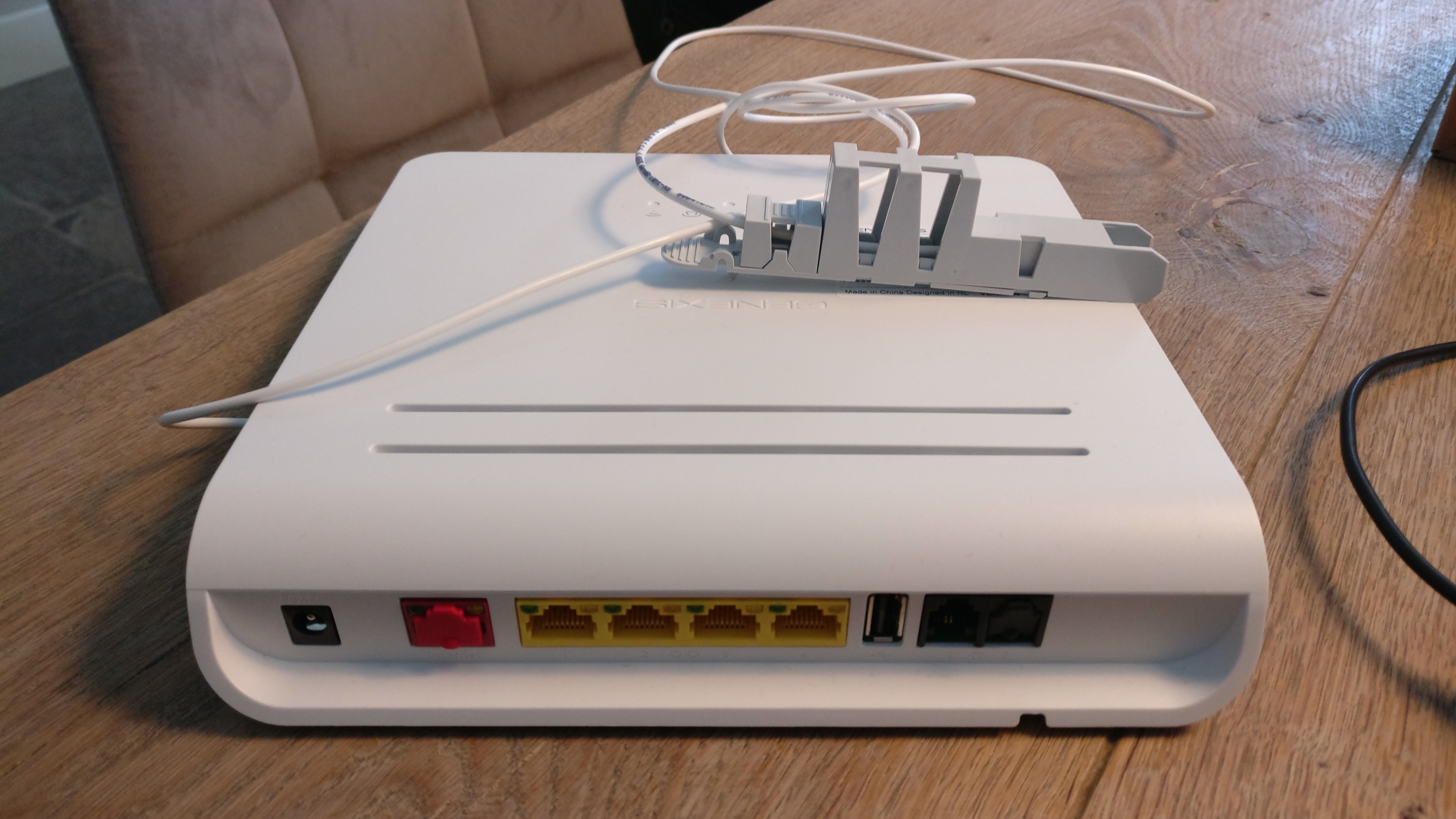
Connect router
Install an UTP (cat 6/7) cable from the POE injector (use the port labeled as ‘LAN’) to the external interface port on the new router, this port is typically labeled as WAN or Internet.
5. Configure router
It’s important to realize that the services provided by Delta/Caiway are delivered using multiple VLANs. Therefor you need to configure multiple VLAN subinterfaces/tags on the external (WAN/Internet) interface/trunk of the router. How to do this depends on the router you have, please check the vendors manual or just click here.
Internet
Internet connectivity is provided on VLAN 100, all you need to do is tag the WAN/Internet interface with VLAN ID 100 and use DHCPv4 for obtaining an IP address. From there it’s business as usual with configuring Network Address Translation (NAT), etc.
IP TV
IPTV is provided on VLAN 101, so just add another tag to the WAN/Internet interface with VLAN ID 101. In general ISPs can provide IP TV in either routed or bridged configurations. At the time of writing I have not figured out what methodology is used currently. I will soon get around to figuring this out and I will then update this blog post.